
Holes stay holes
Loops inside a shape are cut out, and loops inside those holes turn solid again.
Drop a laser, CNC or CAD drawing. Closed shapes turn solid, inner loops stay holes, and you set the thickness in mm. Nothing uploaded.
Built in your browser. Files are never uploaded.
Inspect the drawing, check the finished STL, or make the lettering a DXF cannot carry.
Drop the file or click to choose it. Units come from the file header, and a sample plate is loaded so you can try it first.
Tick the layers to extrude, set the thickness and scale, and add a backing plate if you want raised shapes on a base.
Check the size and the watertight result, then download STL or 3MF and open it in your slicer.
The sample mounting plate as drawn, and after this tool extrudes it.
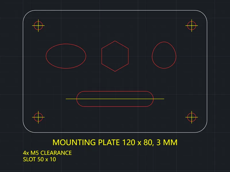
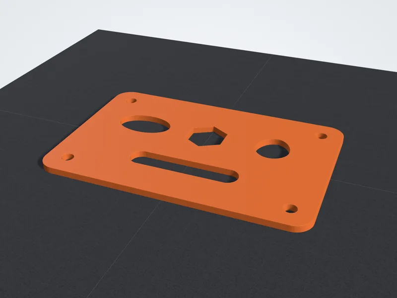
Made for laser, CNC and CAD outlines that need to become printable parts.
Loops inside a shape are cut out, and loops inside those holes turn solid again.
Each layer lists its closed and open shapes. Layers with only text or open lines start unticked.
Loose ends closer than the value you set, up to 2 mm, are joined into closed outlines.
Drawing units come from the DXF header and are converted to millimeters. Pick one when the file has none.
Raise the shapes on a rounded plate that follows the drawing, with your own margin and thickness.
Every edge of the result is counted, and a warning shows when the part is larger than a 256 mm bed.
Four choices that keep a plate flat, stiff and the right size.
An extruded part has a flat bottom, so it prints straight on the bed without supports.
For stiff plates use three or four walls and 20 to 40 percent infill.
Small holes print a little tight. Draw bolt holes 0.2 to 0.4 mm larger, or drill them out.
A 3MF stores millimeters as its unit, so the slicer never has to guess between inches and millimeters.
Drawings made for a laser or CNC print well. Thickness ranges are for PLA or PETG on a 0.4 mm nozzle.
Thickness is the dimension that matters, so measure a test print
0.5 to 3 mmPrint in TPU, slowly, with 100 percent infill
1 to 3 mmTurn on Backing plate for raised letters
3 to 5 mmA thicker plate guides a drill straighter
4 to 10 mmClosed contours, CAD fixes, thickness and slicing in detail.
A 3D print needs a solid with a closed skin, so only shapes whose outline closes on itself can be extruded. Circles, closed polylines and closed splines are closed by definition. Loose lines and arcs are chained end to end, and a chain that returns to its start, within the gap setting, counts as closed.
Inside a closed shape the next loop in is a hole, the loop inside that hole is solid again, and so on. That is how a washer keeps its centre hole and a letter O keeps its counter. Open contours, such as a centre line or an outline with a gap, are skipped and drawn in red on the 2D outline so you can see exactly what is missing.
For tiny gaps, raise Close gaps here. It joins loose ends that are closer than the value you set, up to 2 mm, without changing the rest of the drawing.
For bigger gaps, fix the source. In AutoCAD, JOIN merges touching lines and arcs into one polyline, and BOUNDARY draws a closed polyline around any enclosed area. In LibreCAD or QCAD, snap to the endpoints and redraw the missing piece. In Inkscape, join the end nodes of the path before you export. Delete lines drawn twice on top of each other, and keep dimensions and notes on their own layer so you can leave it out.
These are starting points for PLA or PETG on a 0.4 mm nozzle. Print a small test first when a part has to fit something.
Spacer or shim
Gasket
Stencil
Sign or name plate
Mounting plate
Drill template or jig
Files drawn for a laser or CNC are the easiest win. A plate meant to be cut from 3 mm acrylic can be printed 3 mm thick instead. Typical jobs are mounting plates and brackets, spacers and shims, TPU gaskets, signs and name plates, stencils, drill templates and replacement covers.
TEXT and MTEXT entities are not extruded. Explode text to outlines in your CAD or design program first, or make lettering with the Text to STL tool. Hatches are skipped too, because the boundary lines around them usually carry the shape.
The STL is in millimetres, centred and flat on the bed, so it opens at the right size in Cura, PrusaSlicer, OrcaSlicer or Bambu Studio. 3MF records the unit inside the file, which removes any doubt about inches and millimetres.
Print flat parts face down with no supports. For stiff plates use three or four walls and 20 to 40 percent infill. Small holes often print a little tight, so drill them out or add clearance in the drawing.
Answers about open contours, holes, units, layers and watertight files.